Wafer-level
Test and Burn-in (WLB)
Wafer-level Test and Burn-in
(WLTBI)
refers to
the process of subjecting semiconductor devices to electrical testing
and burn-in
while they are still in wafer form. Burn-in is a temperature/bias
reliability stress test used in detecting and screening out potential
early life failures.
WLTBI
usually employs a
wafer prober
to
supply the necessary electrical excitation to all the die on the wafer
through hundred or thousands of ultrathin probing
needles
that land on the bond pads, balls, or bumps on the die. The
required die temperature elevation, on the other hand, is achieved by
the wafer prober through a built-in
hot plate
that heats up the wafer to the correct junction temperature.
Wafer-level testing and burn-in is applicable not only to: 1) devices
sold as bare die, which are also referred to as
'known good die'
or
'KGD';
and 2)
wafer-level
packaged
devices; but to 3) devices intended for
conventional
packaging as
well. In the third case, WLTBI is performed as a prescreen, so
that only the parts that passed WLTBI will undergo back-end processing,
i.e., assembly and final test.
The ideal
semiconductor manufacturing scenario is to come up with a process that
does everything at wafer level, but its prohibitive costs for now does
not make it viable for all applications just yet. Once perfected,
however, an integrated wafer-level packaging, wafer-level electrical
testing, and wafer-level burn-in will streamline the over-all
semiconductor manufacturing process to a large degree, resulting in
great cost savings and much shorter cycle times.
After all, wafer-level packaging, which
is basically just an extension of the traditional wafer fabrication
process to provide each die on the wafer with a means of interconnecting
to the outside world, would eliminate the need for a separate IC
packaging/assembly line.
In a similar fashion, wafer-level testing and wafer-level burn-in would eliminate the need for
separate equipment for testing and burn-in, since both of them may be
performed on a wafer using the same basic methodology and set-up.
This is not so in the case
of individually packaged IC's, whose electrical testing and burn-in
require
different equipment in different areas on the production floor.
Conventional electrical testing uses expensive automated test equipment
(ATE) on the test floor while conventional burn-in requires burn-in
ovens that are kept in their own burn-in areas due to the large amounts
of heat that they radiate.
Still, the
basic
philosophies
used in testing and burning in individual IC's are
the same
as those used for wafer-level test and burn-in.
Both electrical testing and
burn-in need a means of supplying the devices under test (DUT) with electrical bias
and excitation, whether it's done at wafer level or at package level.
The difference lies in the method of delivering the required electrical
bias and excitation to the devices.
During electrical testing of individual IC's, electrical
bias and excitation are provided by the ATE to the DUT by mechanically
contacting its leads. In conventional burn-in of individual IC's,
the units are placed on burn-in boards which in turn are inserted inside
burn-in ovens. The burn-in ovens provide the electrical bias and
excitation needed by the devices during burn-in through these burn-in
boards.
During
wafer-level testing and burn-in, however, the electrical bias and
excitation required by the devices are delivered
directly
to the interconnection points (the bond pads or the solder balls/bumps
over the bond pads) of each die on the wafer. This can be achieved in a
variety of ways, some of which are discussed in the next page.
Achieving Full Wafer Electrical Contact
The challenge in any
wafer-level testing and burn-in process is being able to use existing
wafer probing technology to contact all the
operation-essential pads of all the die on the wafer at the same time.
This is referred to as
full-wafer
or
whole-wafer contact
technology. The capability to do so will allow
the burn-in process to be conducted to the entire wafer in one
operation.
Once electrical contacts
have been made, wafer-level devices may already be subjected to the same testing
methodology as what their individually packaged counterparts normally
receive. In electrical testing, this may mean subjecting the DUT
to a sequence of test blocks, each of which forces a certain set of
voltage and/or current conditions to the DUT and measures the
corresponding current/voltage/timing response of the DUT
against specifications.
Burn-in, on the other hand,
places the DUT in an electrically stressful condition over a specified
amount of time. Stressful electrical conditions include operating
the device at maximum power dissipation, continuous dynamic switching of
the inputs, application of high reverse bias voltages, and the
like.
In an article by
Dan Inbar and Mark Murin of M-Systems (source: Semiconductor
International, 8/1/2004), the formidability of achieving whole-wafer
contact with today's wafers was explained using a simple example: if a
typical wafer has 500 die, with each
die containing 40 functional pads, then 20,000 probing points are needed to
properly activate all of these die on the wafer during burn-in.
Cramming all of these probe needles onto a single 6" wafer at the same
time without allowing any of them to come into contact is indeed
challenging.
Full-wafer
contact systems currently employ three different methods or technologies:
1) the probe-per-pad
method; 2) the sacrificial
metal method; and 3)
the built-in test/burn-in method.
The example above wherein each pad of each die on the wafer is directly
contacted by an ultra-thin contact pin or needle of a wafer probing
system so that electrical testing may be performed by the test equipment
pertains to the
probe-per-pad
method.
Needless to say, the challenge presented by this method is coming up
with a proper design for an extremely dense array of probes.
In the
sacrificial metal method, a thin layer
of metal is deposited over the entire wafer in patterns that connect
together the equivalent bond pads of groups of die on the wafer, so that
a reduced number of probe needles may be used to excite all the die on
the wafer. After the WLTBI process is completed, this sacrificial layer
is etched away from the wafer. The main drawback of this method is the
need for extra wafer fab steps to deposit and remove the sacrificial
metal layer.
The
built-in test/burn-in method
involves the application of Design-for-Test (DFT) philosophy in the
development of new products. Here, a new device would incorporate
an additional special circuit on the die that would facilitate self-testing and/or self-burn-in
using a relatively smaller number of probes. Such a
circuit might employ serial I/O (to reduce the number of I/O probes
needed) and a built-in test/burn-in subsystem. Wafers of this new
product may then undergo full-wafer contact probing using a much smaller
number of probes.
Challenges in
Wafer Level Test and Burn-in
Aside from the high up-front
costs of developing and setting up the equipment, especially if
full-wafer contact technology is involved, another serious challenge
posed by WLTBI is the achievement of
highly
reliable
and
excellent
electrical contact
between each of the probes and its corresponding bond or test pad (or
bump) on the die.
Poor contact
or loss of contact in the middle of test or burn-in may result in a
multitude of problems: over-rejection, insufficient burn-in, and even
electrical overstress (EOS). Contact failure involving even just a
single pad or bump of the device will cause the test or burn-in to fail.
A wafer probing system with excellent and reliable contact capability
will eliminate yield losses due to contact failures - a necessity in the
ever-competitive semiconductor industry.
Ensuring high
contact integrity and reliability for a large number of probe tips is
not easy though. At the very least, it entails a sound maintenance
routine that consists of monitoring probe tip life, replacing worn-out
tips, and continuous tip-to-pad alignment checks and realignment.
Achieving the
bandwidth required by electrical testing and burn-in of high-speed
devices is also another consideration that needs to be addressed by an
engineer setting up WLTBI capability. Excellent engineering
design
and material selection for the probe needles to be used are a 'must' if
high bandwidth test and burn-in capability is desired.
The initial
steps toward viable wafer-level test and burn-in systems have already
been taken. Still, the journey toward industry-standard WLTBI methods
and equipment will be long and arduous. Obstacles in the way of
standardized WLTBI processes include the large diversity of wafer-level
packaging solutions; the continuous reduction in wafer size and die
interconnection pitches; and the wide availability of conventional test
and burn-in solutions for applications that are not yet ready for WLTBI.
Just the
same, many companies will try to be at the forefront of WLTBI technology
because, to most of them, an integrated wafer-level manufacturing
approach would make the best sense for the future of semiconductor
manufacturing.
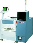
Figure 1.
Example of a Handler for
Wafer-Level
Burn-in
See Also:
Electrical Testing; Burn-in;
Probe/Trim;
Wafer-Level Packaging;
IC
Manufacturing
HOME
Copyright
© 2001-2004
www.EESemi.com.
All Rights Reserved.