Electrical Test
Electrical
testing
is the identification and segregation of electrical failures from a
population of devices. An electrical failure is any unit that does
not meet the electrical specifications defined for the device.
In
simplified terms, electrical testing consists of providing a series of
electrical excitation to the
device under test
(DUT) and measuring the
response of the DUT.
For every set
of electrical stimuli, the measured response is compared to the expected
response, which is usually defined in terms of a lower and an upper
limit. Any DUT that exhibits a
response outside of the expected range of response is considered a
failure.
In production
mode, electrical testing is usually performed using a test system or
platform, consisting of a tester (see Fig. 1) and a handler (see Fig. 2). Such a test system
is also referred to as an
automatic (or
automated) test equipment,
or
ATE.
The tester performs the electrical testing itself, while the handler takes
care of transferring the unit to the test site and positioning it for
proper testing, as well as reloading it back into another tube after the
testing process is completed.
The
testing process executed by the tester is controlled by the
test program
or test software. The test program is usually written in a high
level language such as C++ or Pascal. It consists of a series
of several
test blocks, each of which tests the DUT for a certain
parameter. Every test block sets up the DUT fixtures for proper
testing of the DUT for the corresponding parameter. It also
tells the tester what electrical excitation needs to be applied to
the DUT, as well as the correct timing of applying them.
|
 |
|
Figure 1.
Example of an IC Tester
|
There
are usually two versions of the test program. One is a
production
version and the other is a
quality assurance version. The production
version has stricter limits compared to the QA version, while the QA
version more or less tests the DUT to the datasheet specification limits.
The differences in production and QA limits, or the
guardbands, should be
large enough to take into account errors attributed to over-all testing
variability and noise, but not large enough to result in
over-rejection. If the guardband is chosen properly, any unit
passing the production test is almost sure to pass the datasheet limits,
regardless of which test equipment on the floor is used.
|
 |
|
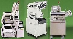
Figure 2.
Three (3) Examples of Test
Handlers (Right) |
The
test program usually consists of two types of test blocks, namely,
parametric and functional.
Functional testing checks if the device
is able to perform its basic operation.
Parametric testing checks if
the device exhibits the correct voltage, current, or power
characteristics, regardless of whether the unit is functional or not.
Parametric testing usually consists of forcing a constant voltage at a
node and measuring the current response (force-voltage-measure-current, or FVMC) at that node, or forcing a constant current at a node and measuring
the voltage response (force-current-measure-voltage, or FCMV).
Electrical
testing is normally done at ambient temperature, but testing at
other
temperatures is also being done depending on the screening requirements.
For instance, latch-up problems have better chances of being detected at
an elevated temperature while hot carrier failures are easier detected at
low temperatures. Aside from 25C, other standard test temperatures
include -40C, 0C, 70C, 85C, 100C, and 125C.
Test Links:
Electrical
Test;
Burn-in;
Marking;
Tape
and Reel;
Dry
Packing;
Boxing
and Labeling
See Also:
Test Glossary;
Test Confidence;
Strip Testing; IC
Manufacturing; Test Equipment; Test Accessories
HOME
Copyright
©
2001-2006
www.EESemi.com.
All Rights Reserved.